A few people have written in to ask if I could post a guide on how to read the distortion pedal schematics on this site. For this article, I am going to briefly describe the various symbols found on the schematics and show you how to build a very basic circuit.

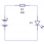
A simple schematic for a circuit that powers an LED light.
The circuit we are going to build is simply a 9v battery connected to a LED light bulb which could be used to power that cool led on your custom distortion pedal. The schematic here shows three components. Starting at the left, we have the battery source, in the case a 9v battery. On the right is the LED which is actually a type of diode (a Light Emitting Diode). Because the LED and 9v battery probably have different specifications, a resistor is shown on top of the schematic which is required to limit the current and reduce the voltage from the 9v battery so that the LED can operate without destroying itself due to being overpowered. This site here will calculate the type of resistor you’ll need. Using a 2v, 220mA LED, the calculator told me a 1.6 Watt capable or greater 33 ohm resistor. The color code for 33 ohms is orange orange black. The mathematical way to calculate the required resistance is to use the formula Resistance = (Power Supply Voltage -LED Voltage ) /LED amperes. In our case, that would be R = (9v-2v/220) or R = ~ 32 ohms so the auto calculator I refereed to above was very close. You can tell a resistor by the bands of colour on it, in our case we are looking for one that has bands of orange, orange and then black.
Starting with the 9v battery’s positive lead wire, we can trace the circuit starting at the left + symbol up to the resistor, then to the LED diode, and then to back to the battery’s negative lead wire. Very simple, right?
Besides resistors and diodes, other symbols you likely find on distortion pedal schematics are for electronic components that include transistors, capacitors, switches, potentiometers (knobs), and op-amps. If you are a novice at this stuff, I would suggest reading the wikipedia articles for each component which shows pictures of the components as well as excellent articles that describe how the parts work and what they do. This should give you an idea of the potential uses for these parts in distortion pedals. Most of the common symbols can be seen here.
 In this picture, you can see what our little circuit would look like if were to solder it onto a board. The battery lead wires would get soldered directly to the board as well as the resistor and diode. When the battery is hooked up, the LED should light up. If you wanted to, you could easily add a switch to this circuit but I will leave that for a future article when I show you how to build a distortion pedal from scratch.
I have a attached a few pictures at the bottom that show my little LED circuit in a working environment on a experimentations breadboard. These cheap little boards can be used to put together working mock projects of small circuits to see how the circuit works before you go ahead and solder it. The connections are completely solderless so you can modify it without having to make a mess by desoldering and resoldering.
I hope this helps you understand how a schematic is read and how a distortion pedal can be custom built. In future articles, I will alter our circuit to include the necessary components to get a working distortion pedal. In the next article, we will add 2 geranium diodes, a transistor, 2 capacitors and 2 more resistors to make an actual working distortion pedal that you can build at home for next to nothing using recycled components or parts bought online or at an electronics supply store like radio shack. The components will cost you less than $20. In the third installment of this series, I will be showing you how to add a volume knob, a distortion knob and a switch and will also be showing how to mount the custom distortion pedal in a project box. For homework, I would suggest reading some articles like this one, this one and this one.


